
Page 16 - Sect1
P. 16
PAGE 16 / NATIONAL CLOTHESLINE / DECEMBER, 2020
WRENCH WORKS
BY BRUCE GROSSMAN
Troubleshooting boilers gone bad III
his month you will learn you’ll notice that the return can of WD-40 or a good pen-
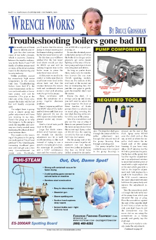
how to identify and re- pump is always running and etrating oil. PUMP COMPONENTS
Tpair the other common the burner is being controlled Be sure the electrical power
cause of low boiler pressure, by the low water level cut off. to the boiler pump is off! Once
which is excessive clearance By this time you will have the boiler is no longer under
between the impeller and race- wished that the low water pressure, get some decent
way in the Burks 5 and 7 CT level alarm would just shut lighting on the area of the re-
family of turbine pumps used the $#&% up and will be turn pump and wipe it down
on many of the return systems making frequent trips to the removing dust and debris.
found in the drycleaning and boiler room to press the As long as you’re down
laundry industry. water level reset switch. there, make sure the ventila-
Unlike problems caused At this point we need to be tion louvers (for our non-
by excessively high water careful to make sure there is French speaking readers,
temperature in the return a sufficient water level in the these are the cutouts at the LOUVERS
tank (see “Troubleshooting return tank and that the end/ends of the motor) are
Boilers Gone Bad II”), the strainer between the return free of obstructing lint. Ad- ADJUSTMENT
water temperature in the re- tank and condensate return just the vise grips to gently RETAINER ADJUSTMENT
NUT
turn tank and outlet of the re- pump is clear and allowing grab the impeller shaft near
turn pump will not be water to get to the pump. the motor. IMPELLER
SHAFT
excessive. (The pipe at the These conditions will Rotate the shaft. If it
inlet side of the check valve mimic the symptoms of a swings easily up and down, REQUIRED TOOLS
nearest the boiler will be hot pump impeller clearance you will need to adjust the
but will hardly evaporate problem. pump impeller. On most of
spit). I know I repeat myself but: these families of Burks
The culprit here is pump You MUST shut off the boiler pumps there is a plastic cap
wear; a simple pump im- and boil down until there is no or metal plug covering the
peller adjustment will have boiler pressure! Do not do rear shaft bearing at the cen-
you running in no time. ANY repairs on a boiler under ter of the rear of the pump.
Here’s the poop as to why pressure under any circum- Take the screwdriver and
this happens. As the pump is stance! pry out the cap or plug if
used, the impeller and race- Here’s a list of tools you’ll there is one present (some of
way are slowly eroded away need for this job: the latest pumps do not have
increasing the physical clear- Large flat blade screw- this access cap). Spray a shot ence. The impeller shaft goes pressed on the end of this
ance between them. driver; small hammer; span- of WD-40 into the opening through the center of this im- shaft. Spray some WD-40
This results in the lower- ner wrench for impeller covered by this cap or plug, peller adjustment nut, over the shaft and on this
ing of the pressure the pump adjustment nut (it is well NOT into the louvers. through the inboard wall of nut, as well as where the im-
can push against (“dead head worth investing in this tool On the pump end of the the pump housing then peller shaft enters the in-
pressure”). No, Grasshopper, instead of trying to use a motor is a round impeller ad- through a rotating seal. board wall of the pump
increasing deadhead pres- punch); vise grip pliers (nee- justment nut (see figure) The pump impeller (not housing. If you have time,
sure will not get you a free dle nose-type if possible); about two inches in diameter visible because it is enclosed allow 10-15 minutes for the
Jerry Garcia-flavored ice and a 5/16” combination that has six blind holes in the pump housing) is WD-40 to penetrate the parts.
cream cone. Eventually, open end/box wrench; spray drilled around its circumfer-
On the face of the pump that
has the impeller adjustment
nut is an adjustment retainer
(a small flat slotted piece of
metal with a right angled tab
at the end which goes into a
hole in the impeller adjust-
ment nut) held in place by a
small 5/16 headed bolt. Use
the 5/16 wrench, unscrew
the small adjustment retainer
bolt from the pump body and
remove the adjustment re-
tainer.
Take the screwdriver, push
it through the hole in the rear
of the pump from which you
removed the cap or plug.
Place the screwdriver against
the end of the impeller shaft
(it will have a screw on the
end; you don’t have to put
the screwdriver into the
screw slot we are using the
screwdriver as a handy
punch) and gently tap the
shaft end.
Now you’re ready to actu-
ally make the adjustment.
Continued on page 18
To learn more, visit www.nationalclothesline.com/ads